Multi-Purpose Booster/Buffer PC Board
A DOZEN CIRCUITS WITH ONE PCB
Please don't post the link to this page on any forum or web site as it is a bonus
intended only for those who have purchased pc boards from AMZ. Thanks.
POWER SUPPLY FILTER
 The circuit shown here is a power input filter that will condition the voltage supply to make it clean, stable and noise-free. You would install it between your power supply and any pedal that is sensitive to noise or hum. The power supply connects to +9v of this pcb and the circuit board output connects to the pedal's positive voltage pad. The circuit shown here is a power input filter that will condition the voltage supply to make it clean, stable and noise-free. You would install it between your power supply and any pedal that is sensitive to noise or hum. The power supply connects to +9v of this pcb and the circuit board output connects to the pedal's positive voltage pad.
Parts List
R2 - Jumper
R3 - 2.2k
R5 - Jumper
R6 - 100k (optional)
R9 - 100 ohms
C1 - 22uF
C3 - Jumper
C4 - 100uF
Q1 - NPN transistor (2N4401 or similar)
All resistors are 1/4w and capacitors are in uF.
Notes: The dc voltage of Out2 to ground should be about 0.65v less than V+, or about 9 - 0.65 = 8.35v
If you pull a lot of current through this circuit, R9 should be a 1w or 2w rated resistor.
5v Regulator
 The power supply circuit can be modified to act as a 5v regulator to supply power to digital chips and circuits that need a stable source. A zener diode is used in place of R4. It does not use much current so it can be any low wattage device such as the 1N5232B. The power supply circuit can be modified to act as a 5v regulator to supply power to digital chips and circuits that need a stable source. A zener diode is used in place of R4. It does not use much current so it can be any low wattage device such as the 1N5232B.
Parts List
R2 - Jumper
R3 - 2.2k
R4 - 5.6v zener diode
R5 - Jumper
R6 - 100k (optional)
R9 - 100 ohms
C1 - 22uF
C3 - Jumper
C4 - 100uF
Q1 - NPN transistor (2N4401 or similar)
All resistors are 1/4w and capacitors are in uF.
Notes: The dc voltage of Out2 to ground should be close to 5v
I suggest that you use the inductor in place of R9 as detailed in the Modifications section below.
78L09 Regulator
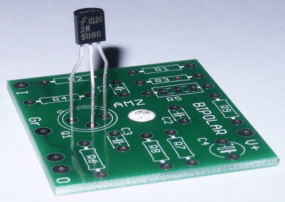
 The Multi-Purpose pc board can even be used as a power supply regulator, utilizing the 78Lxx series integrated circuit in the TO-92 package. The Multi-Purpose pc board can even be used as a power supply regulator, utilizing the 78Lxx series integrated circuit in the TO-92 package.
The relative pin designations for the 78Lxx on this board are: pin 1 = emitter, pin 2 = base and pin 3 = collector. Mount it with the flat side of the TO-92 facing the right side of the board like this.
Parts List
R4 - Jumper
R5 - Jumper
R6 - 1uf capacitor
R9 - Jumper
C3 - Jumper
C4 - 0.33uF
Q1 - 78L09 (or 78L05 as required)
All resistors are 1/4w and capacitors are in uF.
 Notes:The datasheet for the 78Lxx series regulator states that it has a 1.7v dropout, which means that for proper regulation, the input voltage must be 1.7v higher than the regulated output voltage. For the 78L09, the input voltage needs to be 10.7v (9v + 1.7v). For the 78L05, the input voltage required is 6.7v (5v + 1.7v), and so on. Notes:The datasheet for the 78Lxx series regulator states that it has a 1.7v dropout, which means that for proper regulation, the input voltage must be 1.7v higher than the regulated output voltage. For the 78L09, the input voltage needs to be 10.7v (9v + 1.7v). For the 78L05, the input voltage required is 6.7v (5v + 1.7v), and so on.
There are four wire jumpers used for this circuit, so check carefully that they have all been installed. The input to the V+ should be a positive dc voltage.
A 1uF capacitor is used in the position labeled for the R6 resistor. It can be any value from 1uF to 10uF.
The C4 capacitor value is not critical either. It can be any value from 0.33uF to 100uF.
MODIFICATIONS
Use an inductor in the place of R9. A good value is 330uH, rated for at least 100ma. Mouser carries one under their part number 434-22-331.
MORE CIRCUITS
|

