
|
Electra DistortionSimple Vintage Circuit
BASIC PC BOARD
In some of the following circuits on this page, not all parts may be used. If a part is not shown on the schematic or in the parts list for one of the circuits, then it is not required for that project and can be left empty on the pcb.
The parts listed in these instructions are specific to the project that is presented for best performance, and though other parts can be substituted, the capabilities of the may be changed or diminished.
Full Parts List
=========================== All resistors are 1/4w and capacitors are in uF and rated for 25v minimum.
BASIC ELECTRA
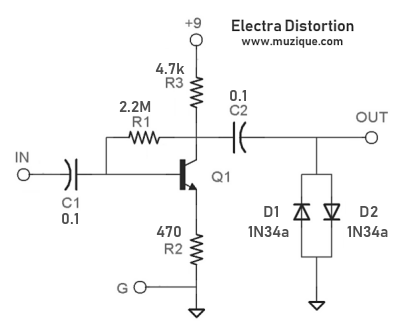
In the basic version, the input and output connections are made directly to potentiometer pads to avoid the use of additional jumper wires. Note that a jumper MUST be used in place of D3.
Vintage Parts List All resistors are 1/4w and capacitors are in uF and rated for 25v minimum. Parts that are not in the parts list are not required for the basic circuit and their positions on the pcb are left empty.
This is the same parts list as the basic Electra shown above but without the D1 and D2 clipping diodes. I suggest that you use the 100k audio taper volume pot so that there is control of how much the signal is boosted. The boost version has been sold by several boutique pedal builders.
 The Bazz Fuss
The Hemmo Bazz Fuss is a simple fuzz circuit that has nasty synth-like tones. It can be built using this pcb with a few changes.
Parts List All resistors are 1/4w and capacitors are in uF and rated for 25v minimum. A wire jumper must be placed in the R2 position. In this fuzz, C1 is an electrolytic capacitor and the plus side should be oriented as shown in the pcb image. A silicon diode is usd in place of R1 and I have drawn a band on the R1 placement in the pcb image to show how it should be oriented. The band is not on the actual pcb. The black band on the diode goes to the same side as the band on R1. This fuzz sounds best when driven hard by the guitar, so the P2 control is not much use. If you do not want to use the P2 Drive control, then you should jumper pad 1 to pad 2 inside the box marked P2. If you cannot find a Schottky diode, then substitute a 100 ohm resistor for D3. Parts that are not used in the parts list are not required for this circuit and their positions on the pcb are left empty. Q1 needs to be a high gain darlington transistor in this circuit. If you cannot find a MPSA13, then try KSP13, MPSA29 or even a 2N5089 or BC550.
When looking through some old archives of schematics, I found a copy of a Usenet post from 1994 that had the original ASCII schematic of the Electra distortion. A diy builder took the circuit from the Electra MPC5 Power Overdrive module and modified it. He then posted that info to Usenet. The famous Electra distortion was never exactly the circuit in one of the MPC modules. The Usenet post follows:
From: bewxxxx@xxxxxxxx.edu (Bruce E.)
Newsgroups: rec.music.makers.builders
Subject: Simple Distortion circuit schematic
Date: 14 May 1994 13:18 CDT
Organization: Texas A&M University OpenVMScluster

Here is a little distortion circuit that I kinda like.  It's very easy to
build and sounds amazingly like an Ibanez tube screamer.  With the exception
of the diodes it is the circuit for the Electra Power Overdrive module (the
one that went inside the guitar--another relic of the '70's).  It's important
to use Germanium diodes to get the right sound.  The voltage out is .4 volts.
If you need more power and less distortion use Silicon diodes, for 1.4 volts
output (you can change the values of the 4.7K and 470 ohm resistors to get
more distortion if you need.  Just tell your electronics friend that it's an
emitter follower and you need more gain).


                            B+= 9v
                            |
                            |
                            /
                            \
                            /  4.7K
                            \
                            /
                    2.3M    |       | |
                   /\/\/\/\-o       | |
                   |        o-------| |--------o-------o---> Out
                   |        /       | |        |       |
                   |    |  /C       | |        |       |
          | |      |    | /                  -----   -----
          | |      |    |/          0.1 mfd   /^\     \./  Both Ge-type
 In >-----| |------o----|  2N3904            -----   -----
          | |        B  |\                     |       |
          | |           | \                    |       |
          0.1 mfd       |  \E                  |---o---|
                            \|                     |
                             |                     |
                             |                ----------
                             |                  -------
                             /                    ---
                             \                     -
                             /
                             \ 470
                             /
                             \
                              |
                              |
                              |
                          ---------
                            -----
                              -
Now for all you electronics types who just said, "Heck, that just hard-clips
the signal.  It'll sound horrible", you should realize that the gain of the
transistor is changing with the signal level, and has the effect of rounding
out the upper lobes of the undistorted wave.  If you don't believe me just put
it in your PCSPICE program and watch what it does.  I don't claim credit for
the circuit--the Electra people came up with the amp, and I was just fiddling
with it and found that this worked well--later on I figured out why.  If you
want an uninverted signal (if you think there is a difference) take the signal
off the emitter instead of the collector.  It might not sound the same,
however.  I didn't test it.

Have fun with it.  Should cost about $10 from Radio Shack components,
including jacks.

Ask me about it if you really really really need to.

Bruce
bewxxxx@xxxxxxxx.edu
|
AMZ-FX Home Page
Lab Notebook Main Page
Guitar Effects Blog
©2020,2023 Jack Orman
All Rights Reserved
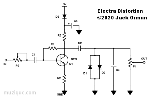
 This is the full schematic to the pc board shown above. The design has been expanded beyond the basic vintage circuit. Power supply protection and filtering have been added, for example.
 This is the wiring for the off-board potentiometers that are used in this version.
 The original Electra did not have any potentiometers for control of volume or distortion. The player used the guitar's volume knob to control the distortion.

