
|
Compressor TestsYour Compressor Is Probably A Limiter©2022 By Jack Orman
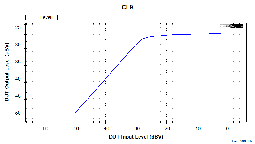
For this second article, I bought several compressors that were based on circuit designs other than the Dynacomp. The first is the Behringer CL9 that is based on the old Ibanez CP9, which was part of the 9-Series that dated from the early 1980s. It is similar to the Dynacomp with a few improvements, but critically it has the same transistor-based detector that generates the control voltage.
The Behringer design has an attack control that was set for fastest response for the tests. Looking at the signal level plot, I have it adjusted for unity gain below the threshold. There is a short knee transistion followed by heavy limiting as in the Dynacomp. As the input signal increases above the threshold, there is very little change in the output voltage. Next up is the Behringer CS400, which is based on the Boss CS3 Compression Sustainer. This design has a slightly more complex detector circuit using a pair of op amps, but critically at its center is the dual bipolar transistor switches that are the main limitation just as in the previous pedals. It also has an attack control that was set at its minimum position.
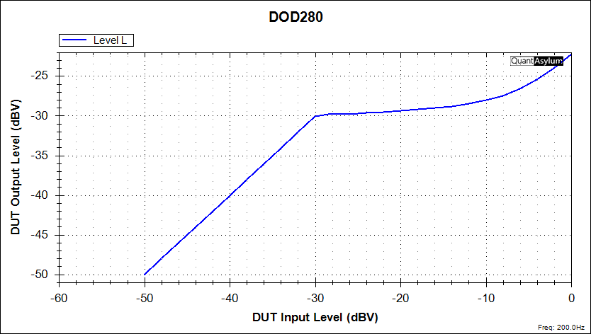
The pedal was adjusted for unity gain below the threhold that was set about -30db in this example. Once the transistors in the detector turn on, the output signal is heavily limited even as the input signal increases in voltage level. This Boss CS3 clone has the same limiter response that was seen in all of the previous pedals. The compression ratio is at least 10:1 and the pedal is acting as a peak limiter. Up to this point, all of the circuits have had voltage-controlled amplifiers that are getting a DC feedback signal derived from the output to control the gain and the resulting compression. What about a different circuit design? Since I already owned a new DOD 280 compressor, it seemed like a good candidate to put on the test rig. The DOD compressor has an electro-optical circuit that varies the gain using a light-dependent resistor driven by an internal LED. The control signal also has the detector connected in a feedback configuration. The graph of the DOD 280 is shown below and it has some interesting differences from the VCA circuits.
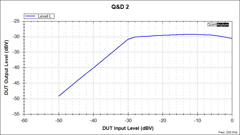
Once again, the output level is set for unity gain for the uncompressed signal. It can be seen that -50db input gives -50db output, and -40db input gives -40db output, up to the threshold that is at -30db. Once the threshold is reached, the internal photo-resistor rapidly turns on and the output signal is again heavily limited. However, for this type of circuit there is an important difference. The photo-resistor is in parallel with the feedback resistor of a non-inverting op amp gain stage. When the LED of the photo-coupler turns on, the resistance of the internal conductive element goes down and the overall gain of the op amp is reduced. This produces the initial limiting action that begins at -30db on the graph above. With this circuit, there is a fundamental limitation. The gain of a non-inverting op amp stage can be no lower than +1 even when the feedback resistance is reduced to 0 ohms - it basically becomes a buffer in that condition. In the DOD 280, the photo-coupler resistance goes down once the output signal has driven its detector transistors into conduction but since the gain can never go below unity, the output signal level begins to rise again, and if the graph were extended, it would be close to a 1:1 ratio when the photo-resistor has reached its minimum resistance. This circuit limitation actually serves to give the pedal a more dynamic reponse on the pick attack, and it will sound less squashed than the VCA based circuits that are going to crush the strongest peak signals. The optical circuit has a softer sound and may even feel more responsive to the player. Even so, the output will be limited after the initial pick attack fades out. While I had the compression test rig set up on the workbench, I decided to plug in my AMZ Q&D 2, which is based on the SSM2166 chip. I calculated that the controls could be set to imitate the Dynacomp action, and it did not take but a couple of tries until I got the following result.
This is a decent imitation of the Dynacomp using a pedal that was not actually designed to be a limiter. Below the -30db threshold it is about 1:1 and above the threshold it has the characterustic limiting action. There is a bit of droop on the very strong signals, but this will not be noticeable since it is only one or two db, and is probably caused by distortion since this chip is powered by only 5 volts.
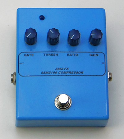
The Gate and Ratio controls are all the way down. The Threshold is about 10 o'clock and the Gain is adjusted as needed. The settings shown will give unity gain below the threshold. The Q&D 2 compressor is not designed as a limiter and it is capable of much different response when the controls are adjusted properly. There will be examples of this in the next article on compression testing. So far, all of the compressor pedals that were tested exhibit peak limiting chracteristics, with the optical-based DOD 280 having am unusual resposne because of its gain structure.
There are other compressor pedals with a different response that is not peak limiting, including a few that will be shown in the next article on compressors.
Here are a couple of extra compression curves that I also made with the test rig. The first is the Kokko compressor that I bought on Amazon. It looks very similar to the Amazon Basics version but the response was different enough to make me think the circuits are not the same. It also has a sharp peak limiting curve so the detector is probably a transistor design as used in the other compressors.
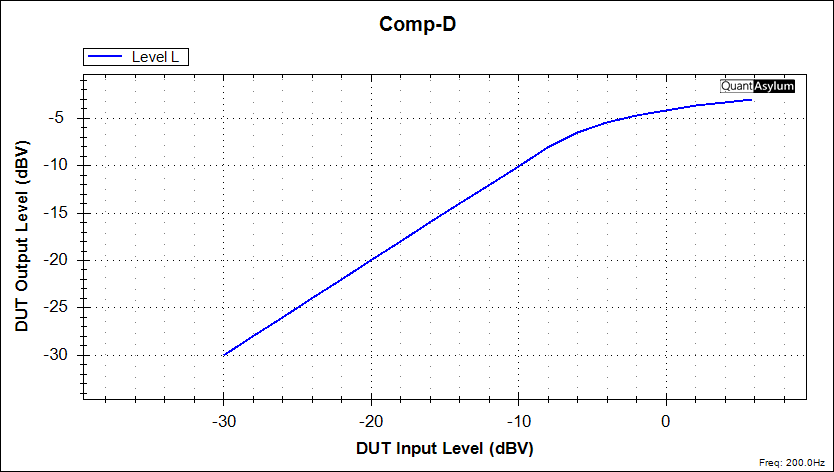
I had trouble getting this pedal to produce the same level output voltage with similar knob settings as the other, so there are some internal differences. I would not select the Kokko pedal as a first choice for a compressor. A final secret curve that was traced is shown below:
There is no compression up to -10db so the ratio is 1:1. The threshold is not adjustable and there is also a very soft knee as the signal response transistions from unity gain to limiting. This circuit would be very transparent and is simple to make. It has given me an idea for a new pedal, and I will reveal the full schematic in a future article. If you have not read the first article on compression testing, you should look at it for additional information, or you can go on to Part 3 of this series. Share this article with your Twitter followers: Tweet See more pix on my Instagram page.
|


 If have one of my
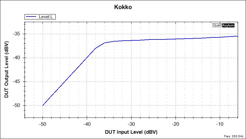
AMZ-FX Home Page
Lab Notebook Main Page
Guitar Effects Blog
©2022 Jack Orman
All Rights Reserved