
|
Compressor TestsYour Compressor Is Probably A Limiter©2021 By Jack Orman
The most copied circuit design has to be the classic MXR Dynacomp that is offered as a clone by practicaly every company that has a pedal compressor. All of these similar designs share a common response with regard to the compression ratio and the knee transistion.
We should first look at the response of a gain circuit as a reference for comparison with the compressor output. In the example shown below, the input signal level is on the X-axis going from left to right while the output level is plotted on the vertical axis.
Looking at the signal level plot, we can see that the input signal is the same as the output level over the entire graph, which means that this is a unity gain circuit (gain=1). For example, a -40db input signal gives -40db output, -30db input signal gives -30db output, -20db input signal gives -20db output and so on. The output/input plotted line is completely straight from low to high audio voltages, so this is a linear gain circuit with no compression. If there is no compression of the signal, it would have a 1:1 ratio. A trace of the same circuit with some gain applied can be tested as a reference. In the graph below, the unity gain buffer signal is the blue trace and the red line is the op amp adjusted for +10db of gain.
On the gain line, a -40db input signal gives -30db output, -30db input signal gives -20db output, and so on. There is a 10db difference between the input and output, with the output signal always 10db stronger than the input signal. The lines are parallel since the response is very linear and consistent. This is still a 1:1 ratio since a decibel increase on the input has an equal effect on the output, even though there is gain. For example, if the input signal increases from -30db to -20db, the amplified output increases from -20db to -10db. However, the input increased by 10db, and the output also goes up by 10db, so the ratio remains 1:1. It is the ratio of the change in signal levels that is used to calculate the compression and not the fixed signal level at any one point. If we plot the gain response of a compressor pedal, the result is much different.
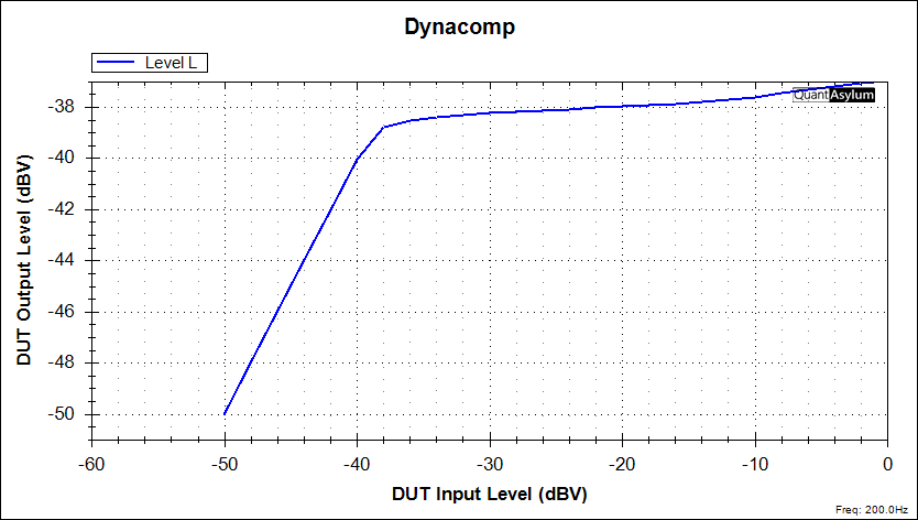
A buffer is unity gain and each decibel of increase at the input produces a matching 1db increase on the output, and there is no compression. This is shown by the blue line on the above graph. With a compressor circuit, the threshold is the input level at which the gain control circuit of the compressor begins to act on the signal to reduce its volume. Above the threshold the signal is compressed but below it there is no effect on the dynamics. A typical compressor response is shown in red on the graph. The compression ratio is a measure of the change in output volume that occurs as the input signal increases. If the input signal has to incresae 2db to produce a 1db rise in the output, then it is a 2:1 ratio. If it takes a 4db change on the input to produce a 1db increase on the output, then it is a 4:1 ratio. High compression ratios of 10:1 or more are typical of limiter circuits. As an example, the graph below shows a the signal from a Dynacomp clone that I made, and the plotted line is quite different than the op amp buffer illustrated in the first graph on this page.
The signals on the input and output at -40db and below are equal, so there is unity gain. However, beginning at -40db, the output signal level does not respond in a linear manner. The signal strength is reduced slightly as the input increases and at -38db the output voltage begins to be heavily limited. To illustrate, note that as the input signal goes from -30db to -20db (10db change); there is barely a 1db increase in the output signal. This means that the ratio is about 10:1 since it takes a 10db change on the input to yield a 1db increase on the output. I have the Sustain (Threshold) control on the pedal set for about -40db but there is no control over the compression ratio in this design. It will always be around 10:1 no matter where the Threshold is set. The high ratio is charateristic of a limiter while compressors are usually less than 10:1. In this pedal, the ratio is decreasing to about 8:1 as the signal strength goes above -10db because the CA3080 OTA chip and transistor detectors are running out of control range. This type of dynamic range control is called peak limiting, since the signals below the threashold are unaffected and only the peaks are squashed when the threshold is exceeded and the gain reduction begins. One well known Dynacomp derivative is the Keeley Compressor, so I bought a used model made in 2007 to compare to my clone. The response plot is below.
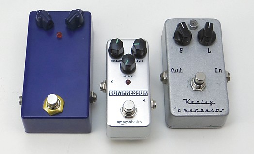
The response curve of the Keeley is virtually identical to that from the clone pedal. There is a difference in gain but that is due to the setting of the output volume control and it does not influence the compression ratio or threshold. The limiting action is clearly visible in the graph. Another compressor pedal that I bought recently was the Amazon Basics Compressor. I do not know anything about the design of the circuit in this pedal but a graph of its response will tell us something about it.
Look familiar? The limiting action and response curve is very similar to my Dynacomp clone. Even the ratio change at high signal levels is much the same. The threshold is slightly different because the pedals have no calibrated markings around the knobs to help set an exact amount, so the controls may have been in slightly different positions or the pots may not have similar tapers or values. There is no guarantee that the Amazon pedal is a Dynacomp clone, but at the very least, it is using a similar transistor-based detector circuit to produce the control voltage. How does this pedal design, which is clearly a limiter, perform well for so many players who have used it? First, the guitar is a very dynamic instrument with a large difference in signal levels between soft and hard picked notes. Also, the initial pick attack is a strong voltage impulse that rapidly decreases to a lower voltgae as the note decays. A player with a Dynacomp type pedal can adjust the Sustain or Compression control so that the strong peaks are squashed but the limiting action quickly returns to normal linear gain as the signal level drops below the compression threshold. With careful adjustment of the controls, only the peaks are limited and the dynamic range is compressed, which is what the player hears.
In the second part of this look at compressor pedals, I show the response of a few other common compressors with different circuit designs.
Share this article with your Twitter followers: Tweet See more pix on my Instagram page.
|
 There are dozens and maybe hundreds of compressor pedals available from a wide selection of manufacturers, many of whom offer more than one model or design. There is even a page of compressor pedal reviews
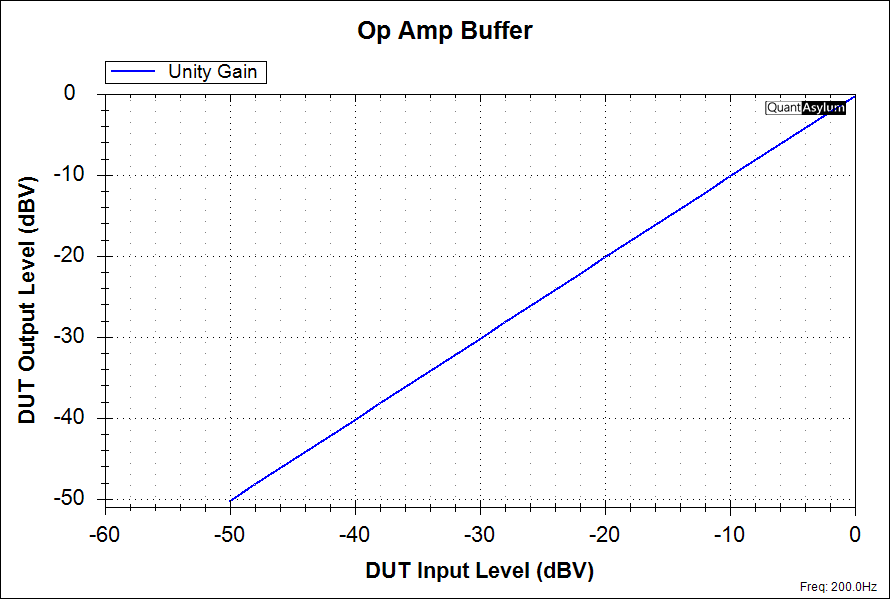


AMZ-FX Home Page
Lab Notebook Main Page
Guitar Effects Blog
©2021 Jack Orman
All Rights Reserved