

True Bypass PC BoardMicroprocessor Controlled Relay
BASIC PC BOARD
Another application of the circuit would be to build a bypass box that can then be used with any pedal without going inside it and modifying the circuit, which could reduce its collectable value.
This design of a microprocessor-controlled-relay was developed several years ago for use with rack equipment that I was building, and has now been adapted to pedal use.
The bypass circuit draws slightly over 4 ma. at idle (LED off) with the current draw briefly rising when the switch is hit to toggle the relay. Except for the 2 ms. when the pulse is applied by the AVR, the relay is drawing no current.
The AMZ Bypass project eliminates two sources of nasty clicks that are often heard with the 3PDT true bypass switches: mechanical clunks as the heavy spring-loaded switch connections toggle, and the LED surge as it is powered up via the switch contacts.
The switching should be click-free, but you may require pulldown resistors on the input and output of the FX circuit to get completely silent switching. Note that the relay makes a very tiny "tick" sound inside the pedal when it actuates.
The pre-programmed AVR is included with purchase of the pc board. No special programming knowledge is needed; just solder in the micro and go. The design was recently revised to allow the selection of the default condition of the relay at startup. Jumpering the optional control pads will make the pedal start with the effect on when first powered up, and no jumper will default to the effect circuit off at startup.
At the time of its introduction, this is the only true bypass relay system using an AVR microprocessor.
I conducted a reliability test on the AMZ true bypass system, and subjected two completed boards to 100,000 cycles of switching. The boards passes the test with 100% reliability. Read more about the details of this flawless performance.
The bypass board will blink the LED twice when it is initializing to let you know that it is working properly. The relay is switched off and the effect is bypassed when it is first powered up (unless the optional jumper is used.)
Complete details on wiring the bypass board, and mods to use it for different purposes are emailed to everyone who purchases the board.
The diagram below shows the basic connections to the AMZ Bypass pcb. A complete parts list is available, which can be used with the Mouser Bill-of-Materials tool to order the parts needed to complete the project.
CONNECTIONS
The L pad is the drive for the LED indicator.
The Sw connection and the Gr (ground) next to it should be connected to the momentary footswitch.
The other Gr pad is wired to the common ground point used by the fx circuit. I usually solder it to the ground lug on one of the signal jacks.
The final 4 pads are the audio signal connections. The I and O should go to the input and output jacks respectively. The S is the send, which connects to the input of the effects pcb, and R is the receive. It goes to the output of the effects circuit.
OTHER PARTS
IC1 is the pre-programmed AVR microprocessor that is included with the pcb purchase.
IC2 is a voltage regulator that is used to reduce the 9v pedal supply down to the 5v needed by the micro.
RY1 is a latching DPDT relay. This means the relay has a coil, that when pulsed by a small voltage, will toggle the relay contacts in the same manner as a DPDT switch. The relay latches in its set condition and does not require constant application of voltage to hold it in either position.
C1 and C2 are voltage filtering capacitors to help out the voltage regulator. C3 is part of the switch debounce circuit and is optional.
R1 is the current limiting resistor for the external LED indicator. The L pad connects to the anode of the LED and the other LED leg (cathode) connects to circuit ground.
R2 and R3 are pull-up resistors for interface with the AVR.
OEM CHIPS
The pre-programmed microprocessor is available to pedal builders who may want to incorporate the bypass-relay design into their pedals. Mimimum quantity for one order is 50 chips, and special pricing is available. Write me for the details.
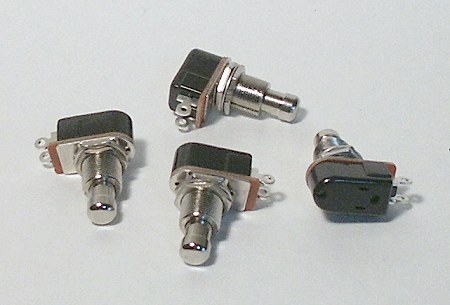
SWITCH
Almost any momentary normally-open switch can be used with this project, and I have used 69 cent plastic panel switches on some of my home rack units, and they performed perfectly well. Our parts ordering page has a suitable heavy duty switch for $3.99.
If the switch is to be placed on a rack panel where it can be actuated by hand, numerous switches are available to do the job. All that is required is a momentary switch that is normally OFF. The switch mechanism can even be a mercury tilt switch, Hall sensor, photocell or any number of other types of devices that can pull the Sw pad connection to ground. Even a quick pulse from a microprocessor or CMOS circuit can trigger the bypass circuit. The reliablity test was conducted by using an Arduino to toggle the footswitch control line.
Click here to see a shot of a pedal that has been retrofit with the bypass pcb. The original DPDT was removed and the new pcb placed between the jacks.
I have added instructions on the relay bypass support page on how to control multiple bypasses with a single momentary switch. You can even toggle between two circuits with one switch. The code in the micro has been revised to add a little tolerance to support multiple switches. The support page is available to everyone who purchases the AMZ relay bypass.
UPDATE Also I have had a report of problems with a boards not wanting to switch and this was traced to cheap relays bought from surplus outlets, which do not meet the minimum standards on the relay datasheet. The code in the microprocessor has been updated to make sure that even out-of-spec relays will switch reliably. All micros shipped from the beginning of 2012 have the latest code.
ORDERING INFORMATION
|
 The AMZ Bypass pcb is a small (1" by 1") circuit board that contains an AVR microprocessor and a latching relay, which can be used with a soft-touch momentary switch to add true bypass to a new effects build, or even retrofit into an existing pedal. It can be used to upgrade Boss or Ibanez pedals from jfet switching to true bypass.
 A lot of work went into developing the assembly language code for the microprocessor, which includes switch debounce and noise immunity. The micro can also detect if you are holding the switch down, which it will ignore. There is even some code that makes sure that the LED status and relay position do not get out of sync.
 The + pads are for +9v power. The two pads are connected togther on the pcb and provide a loop through the board if needed. Either can be left unconnected if not used.
 A heavy-duty momentary footswitch is recommended for this circuit. Suitable units are made by GC and CARLING (110-PM-OFF), and less expensive switches are available from most online pedal parts suppliers.
©2010-2012 Jack Orman
All Rights Reserved
Not for Posting on Any Web Site
AMZ-FX Home Page Lab Notebook Main Page Guitar Effects Blog