The free graphics site has been updated and now has hundreds of free images for your DIY pedals. Enjoy!
https://www.instagram.com/amzfx2/
Best regards, Jack

The free graphics site has been updated and now has hundreds of free images for your DIY pedals. Enjoy!
https://www.instagram.com/amzfx2/
Best regards, Jack
I added a lot of images to the site over the weekend. Check it out!

I have created a new Instagram page with free graphics for use on your DIY pedals. (not for commercial use!) There is not much there at this time but I will be adding more soon.
Check it out, and send me a photo if you use one of the graphics.
https://www.instagram.com/amzfx2/


The Mini-Booster assembled modules are on sale for 20% off the regular price!
Get one while they are still available.

For my own use, I made a calculator for finding the frequency of an oscillator using the classic LM555 timer chip. You can find it in the Lab Notebook or here is the direct link:
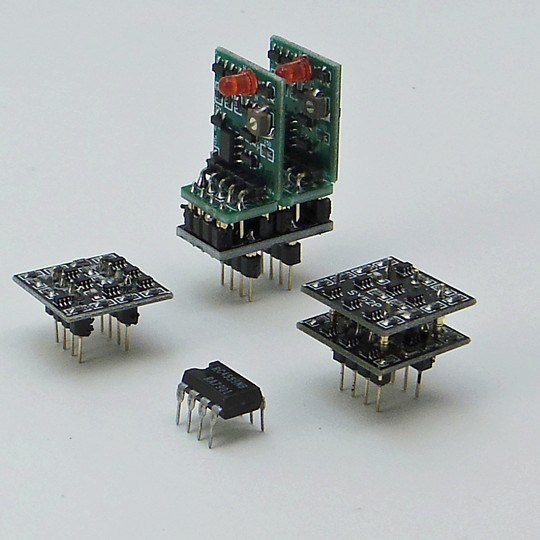
Three dual op amps and a single. More info and images in my Instagram:
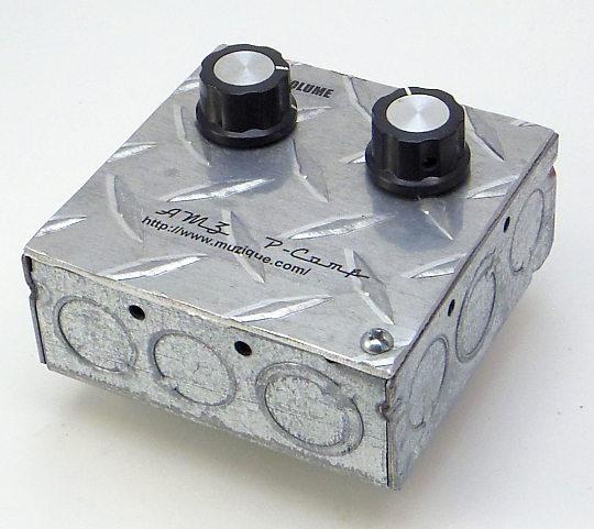
Another pedal prototype in a metal electrical box from around 2000. This box is interesting because I did not have a metal cover for it, so I made one from a piece of aluminum diamond plate that I had in my shop.
More info and images in my Instagram: https://www.instagram.com/amzfx/
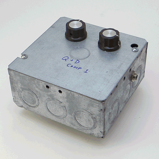
The prototype of the Q&D 1 compressor. The schematic is still on my web site somewhere. It used the SSM2165 vca chip which is unobtanium these days.
More info and images in my Instagram: https://www.instagram.com/amzfx/
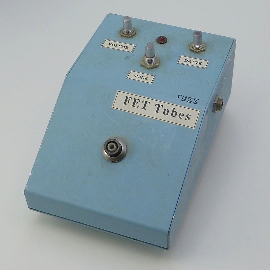
Another ancient pedal from the boxes in my garage. This one has the same type LMB folded aluminum enclosure. It also uses the cmos switching system with a soft-touch footswitch.
More pix and info in my Instagram: https://www.instagram.com/amzfx/
View a Random Post
from the archive.


Jack Orman has been involved in FX design and construction since the mid-1970s.